15
ELECTRICAL SPECIFICATIONS
Resolution
100, 360, 500, 1000, 1024, 2048, 4096 PPR
Counting frequency
50 kHz max.
Output signals
AB0 and /A/B/0
Output circuit
Smart Push-Pull & Line Driver
Power supply
5 – 30 Vdc
Consumption
50 mA max.
Output current
40 mA max (per each channel)
Connection
8-poles shielded cable 1.5m (on encoder side)
Protection
Polarity inversion and short circuit
EMC
According to EN61000-6-2 and EN61000-6-4
Light source
Ga-Al diodes
Optoelectronic life
> 100.000 hrs
ECTIONS
Signal
A
/A
B
/B
0
/0
+Vdc
0Vdc
Ground
Wire
Green
Yellow
Gray
Blue
Red
Brown
White
Shield
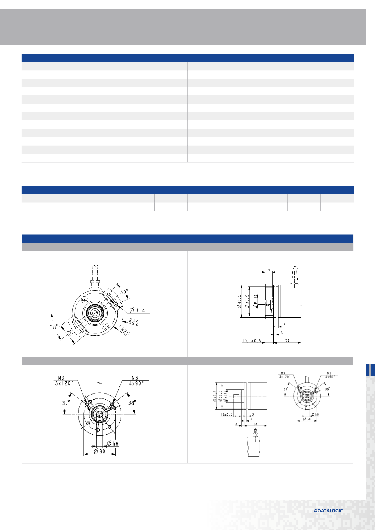
DIMENSIONS
HOLLOW SHAFT VERSION
SOLID SHAFT VERSION
additional code (optional)
I40
I41
CK41
CK46
-
X
a
-
XXXX
b
XXX
c
X
d
XX
e
X
f
X
g
XX
h
Order code
CK41
I40
I41
-
X
a
-
XXXX
b
XXX
c
X
d
XX
e
X
f
X
g
XX
h
X
i
/Sxxx
j
order code
additional code (optional)
a
oUtpUt cIrcUItS
n =
NPN o.c.
p =
PNP o.c.
Y =
Push Pull
l =
Line Driver (RS422)
h =
PP/LD universal circuit
b
reSolUtIon (ppr)
See electrical specifications
c
oUtpUt SIGnal
Bnf =
AB
BcU =
AB, /AB
Znf =
AB0
ZcU =
AB0, /AB0
d
poWer SUpplY
1 =
+5V±5% (L output circuit)
2 =
+10V÷ +30V (Y, N, P output circuit)
4 =
+5V÷ +30V (H output)
e
Shaft DIameter
6 =
6 mm
p6 =
6.35 mm - 1/4”
f
protectIon
- =
IP64
p =
IP65
Q =
IP66 protection shaft side (only I41)
g
connectIon poSItIon
- =
axial
r =
radial
h
connectIonS
- =
1 m cable
l2 =
2 m cable
lx =
x m cable
i
c =
Inline connector DSub 9 pin
I40
I41


