19
ELECTRICAL SPECIFICATIONS
Resolution
500, 1000, 1024, 2000, 2048, 2500, 5000, 10000 PPR and programmable
Counting frequency
100 kHz max.
Output signals
AB0 and /A/B/0
Output circuit
Smart Push-Pull & Line Driver
Power supply
5 – 30 Vdc
Consumption
70 mA max.
Output current
40 mA max (per each channel)
Connection
8-poles shielded cable 1.5m or connector M12 or M23
Protection
Polarity inversion and short circuit
EMC
According to EN61000-6-2 and EN61000-6-4
Light source
Ga-Al diodes
Optoelectronic life
> 100.000 hrs
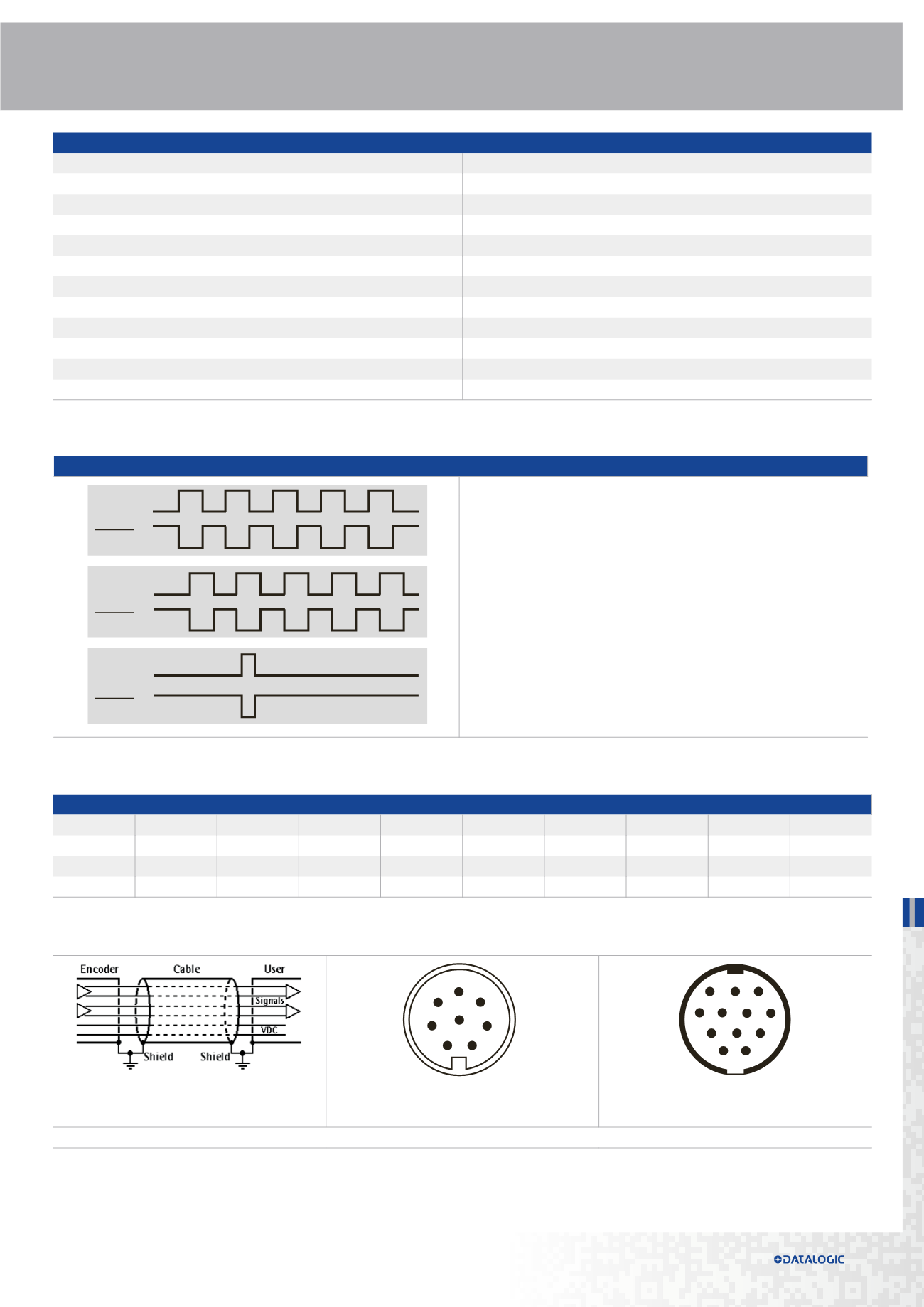
OUTPUT SIGNALS
The incremental encoders supply A and B, 90° phase shifted signals, and their rela-
ted complement outputs.
A single channel can provide the rotation speed only, whereas two phase shifted
channels can give also the rotation direction and increase resolution.
The 0 index is used as reference mark for the "home" position.
NOTE: view and pin-out of the connectors on the encoder side
Track A
Track A
Track B
Zero pulse
Track B
Zero pulse
ELECTRICAL CONNECTIONS
Signal
A
/A
B
/B
0
/0
+Vdc
0Vdc
Ground
Wire
Green
Yellow
Gray
Pink
Blue
Red
Brown
White
Shield
M12 pin
3
4
5
6
7
8
2
1
Case
M23 pin
3
4
5
6
7
8
2
1
Case
8-poles cable
M12 8-pin connector
M23 12-pin connector cw
(only 8 pins are used)
4
5
6
7
1
8 3
2
8 9 1
10 2
11
12 7
6
5 4
3


